
Product Description
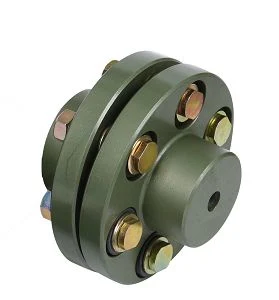
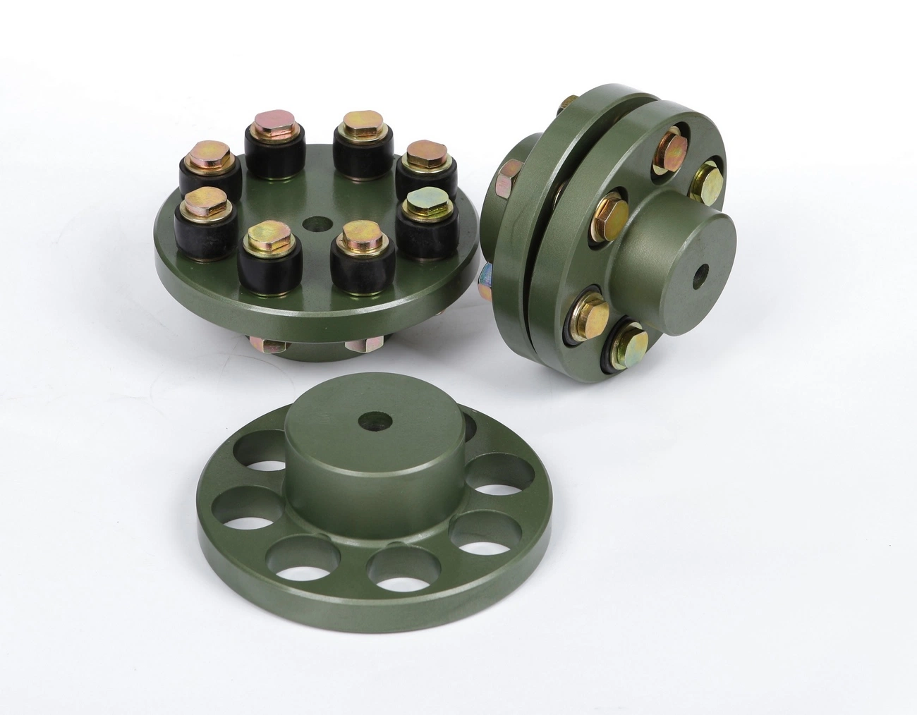
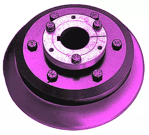
GFC-20×25 Type Aluminum Alloy Shaft Flange Coupling Flexible Shaft Coupling
Description of GFC-20×25 Type Aluminum Alloy Shaft Flange Coupling Flexible Shaft Coupling
| model parameter | common bore diameter d1,d2 | ΦD | L | LF | LP | F | M | tightening screw torque (N.M) |
| GFC-14X22 | 3,4,5,6,6.35 | 14 | 22 | 14.3 | 6.6 | 5.0 | M2.5 | 1.0 |
| GFC-20×25 | 3,4,5,6,6.35,7,8,9,9.525,10 | 20 | 25 | 16.7 | 8.6 | 5.9 | M3 | 1.5 |
| GFC-20X30 | 3,4,5,6,6.35,7,8,9,9.525,10 | 20 | 30 | 19.25 | 8.6 | 5.9 | M3 | 1.5 |
| GFC-25X30 | 4,5,6,6.35,7,8,9,9.525,10,11,12 | 25 | 30 | 20.82 | 11.6 | 8.5 | M4 | 2.5 |
| GFC-25X34 | 4,5,6,6.35,7,8,9,9.525,10,11,12 | 25 | 34 | 22.82 | 11.6 | 8.5 | M4 | 2.5 |
| GFC-30×35 | 5,6,6.35,7,8,9,10,11,12,12.7,14,15,16 | 30 | 35 | 23 | 11.5 | 10 | M4 | 2.5 |
| GFC-30X40 | 5,6,6.35,7,8,9,10,11,12,12.7,14,15,16 | 30 | 40 | 25 | 11.5 | 10 | M4 | 2.5 |
| GFC-40X50 | 6,8,9,10,11,12,12.7,14,15,16,17,18,19,20,22,24 | 40 | 50 | 32.1 | 14.5 | 14 | M5 | 7 |
| GFC-40X55 | 6,8,9,10,11,12,12.7,14,15,16,17,18,19,20,22,24 | 40 | 55 | 34.5 | 14.5 | 14 | M5 | 7 |
| GFC-40X66 | 6,8,910,11,12,12.7,14,15,16,17,18,19,20,22,24 | 40 | 66 | 40 | 14.5 | 14 | M5 | 7 |
| GFC-55X49 | 10,11,12,12.7,14,15,16,17,18,19,20,22,24,25,28,30,32 | 55 | 49 | 32 | 16.1 | 13.5 | M6 | 12 |
| GFC-55X78 | 8,10,12,12.7,14,15,16,17,18,19,20,22,24,25,28,30,32 | 55 | 78 | 46.4 | 16.1 | 19 | M6 | 12 |
| GFC-65X80 | 14,15,16,17,18,19,20,22,24,25,28,30,32,35,38,40 | 65 | 80 | 48.5 | 17.3 | 14 | M8 | 20 |
| GFC-65X90 | 14,15,16,17,18,19,20,22,24,25,28,30,32,35,38,40 | 65 | 90 | 53.5 | 17.3 | 22.5 | M8 | 20 |
| GFC-80X114 | 19,20,22,24,25,28,30,32,35,38,40,42,45 | 80 | 114 | 68 | 22.5 | 16 | M8 | 20 |
| GFC-95X126 | 19,20,22,24,25,28,30,32,35,38,40,42,45,50,55 | 95 | 126 | 74.5 | 24 | 18 | M10 | 30 |
| model parameter | Rated torque (N.M)* |
allowable eccentricity (mm)* |
allowable deflection angle (°)* |
allowable axial deviation (mm)* |
maximum speed rpm |
static torsional stiffness (N.M/rad) |
moment of inertia (Kg.M2) |
Material of shaft sleeve | Material of shrapnel | surface treatment | weight (g) |
| GFC-14X22 | 5.0 | 0.1 | 1 | ±02 | 10000 | 50 | 1.0×10⁻⁶ | High strength aluminum alloy | Polyurethane imported from Germany | Anodizing treatment | 10 |
| GFC-20X25 | 5.0 | 0.1 | 1 | ±02 | 10000 | 50 | 1.0×10⁻⁶ | 15 | |||
| GFC-20X30 | 5.0 | 0.1 | 1 | ^02 | 10000 | 53 | 1.1×10⁻⁶ | 19 | |||
| GFC-25X30 | 10 | 0.1 | 1 | 10000 | 90 | 5.2X10⁻⁶ | 33 | ||||
| GFC-25X34 | 10 | 0.1 | 1 | £)2 | 10000 | 90 | 5.2×10⁻⁶ | 42 | |||
| GFC-30X35 | 12.5 | 0.1 | 1 | ±02 | 10000 | 123 | 6.2×10⁻⁶ | 50 | |||
| GFC-30×40 | 12.5 | 0.1 | 1 | 102 | 10000 | 123 | 6.2×10⁻⁶ | 60 | |||
| GFC-40X50 | 17 | 0.1 | 1 | 8000 | 1100 | 3.8×10⁻⁵ | 115 | ||||
| GFC-40X55 | 17 | 0.1 | 1 | ±02 | 8000 | 1100 | 3.8×10⁻⁵ | 127 | |||
| GFC-40X66 | 17 | 0.1 | 1 | 7000 | 1140 | 3.9×10⁻⁵ | 154 | ||||
| GFC-55X49 | 45 | 0.1 | 1 | ±02 | 6500 | 2350 | 1.6×10⁻³ | 241 | |||
| GFC-55X78 | 45 | 0.1 | 1 | 102 | 6000 | 2500 | 1.6×10⁻³ | 341 | |||
| GFC-65X80 | 108 | 0.1 | 1 | ±02 | 5500 | 4500 | 3.8×10⁻³ | 433 | |||
| GFC-65X90 | 108 | 0.1 | 1 | ±02 | 5500 | 4800 | 3.8×10⁻³ | 583 | |||
| GFC-80X114 | 145 | 0.1 | 1 | £)2 | 4500 | 5000 | 1.8×10⁻³ | 1650 | |||
| GFC-95X126 | 250 | 0.1 | 1 | ±02 | 4000 | 5000 | 2.0×10⁻³ | 1000 |
/* March 10, 2571 17:59:20 */!function(){function s(e,r){var a,o={};try{e&&e.split(“,”).forEach(function(e,t){e&&(a=e.match(/(.*?):(.*)$/))&&1
What are the key features to look for when purchasing a flexible coupling?
When purchasing a flexible coupling, several key features should be considered to ensure it meets the specific requirements of the application and provides reliable performance. The following are the key features to look for:
- 1. Type of Coupling: There are different types of flexible couplings available, such as jaw couplings, beam couplings, bellows couplings, disc couplings, and more. Each type has its advantages and limitations, so choosing the right type depends on factors like misalignment compensation needed, torque capacity, and application requirements.
- 2. Material: The material of the coupling is crucial for its durability and performance. Common materials include stainless steel, aluminum, steel, and various elastomers. Select a material that can withstand the environmental conditions, loads, and temperature ranges of the application.
- 3. Size and Dimensions: Ensure that the coupling’s size and dimensions match the shaft sizes and available space in the system. Oversized or undersized couplings may lead to inefficiencies, misalignment, and reduced performance.
- 4. Torque Rating: Consider the maximum torque the coupling can handle to ensure it can transmit the required power without failure or damage.
- 5. Speed Rating: Check the coupling’s maximum rotational speed capability to ensure it can handle the desired operating speed without issues.
- 6. Misalignment Compensation: Different couplings offer varying degrees of misalignment compensation, such as angular, parallel, and axial misalignment. Choose a coupling that can accommodate the expected misalignments in the system.
- 7. Backlash: For precision applications, consider couplings with minimal or zero-backlash to prevent motion inaccuracies and ensure precise positioning.
- 8. Operating Environment: Assess the environmental conditions, including temperature, humidity, dust, and chemical exposure, and select a coupling with suitable resistance to these factors.
- 9. Maintenance: Decide whether maintenance-free couplings or those requiring periodic lubrication align better with the application’s requirements and maintenance schedule.
- 10. Electrical Isolation: If required, choose couplings with electrical isolation features to prevent current flow between connected shafts.
- 11. Dynamic Behavior: Evaluate the coupling’s dynamic performance, including resonance and damping characteristics, to ensure smooth operation under various loads and speeds.
- 12. Application Compatibility: Verify that the selected coupling is suitable for the specific application, such as pumps, compressors, robotics, automation, or other industrial processes.
Summary: When purchasing a flexible coupling, consider factors such as the type of coupling, material, size, torque rating, speed rating, misalignment compensation, backlash, operating environment, maintenance, electrical isolation, dynamic behavior, and application compatibility. Careful consideration of these features will ensure that the coupling meets the demands of the application, provides reliable performance, and contributes to the overall efficiency of the mechanical system.
How does a flexible coupling contribute to reducing maintenance and downtime costs?
A flexible coupling plays a significant role in reducing maintenance and downtime costs in mechanical systems. Here are the ways in which it achieves this:
- Misalignment Compensation: Flexible couplings can accommodate both angular and parallel misalignments between shafts. By absorbing and compensating for misalignment, they reduce wear and stress on connected equipment, minimizing the risk of premature failures and the need for frequent adjustments.
- Vibration Damping: Flexible couplings dampen vibrations and shock loads in the system. This not only protects the connected components from excessive wear but also reduces the likelihood of damage to bearings, seals, and other critical parts, which would otherwise require frequent replacement or repair.
- Protection Against Shock Loads: In applications where sudden starts, stops, or load fluctuations occur, flexible couplings can absorb and dissipate some of the shock loads, preventing potential damage to machinery. This feature extends the equipment’s lifespan and minimizes unplanned downtime.
- Longevity of Components: By reducing stress and wear on connected components, flexible couplings contribute to their longevity. Components such as bearings, shafts, and gears are subject to less strain and fatigue, resulting in extended service intervals and reduced replacement costs.
- Easy Installation and Maintenance: Flexible couplings are relatively easy to install and require minimal maintenance. Routine inspections to check for wear or damage can be done without significant downtime, allowing proactive maintenance to address any issues before they escalate.
- Adaptability to Operating Conditions: Flexible couplings can handle variations in operating conditions, such as temperature fluctuations and different types of loads. Their ability to accommodate changing conditions reduces the need for frequent adjustments or component replacements due to environmental factors.
- Reduced Downtime during Maintenance: In the event of maintenance or equipment repairs, flexible couplings can be quickly disconnected and reconnected, minimizing the downtime required for servicing. This quick replacement reduces production losses and improves overall system efficiency.
Overall, the use of flexible couplings in mechanical systems promotes reliability, extends the life of equipment, and helps prevent costly breakdowns. By reducing maintenance and downtime costs, flexible couplings contribute to improved productivity and profitability for industrial operations.
What is a flexible coupling and how does it work?
A flexible coupling is a mechanical device used to connect two shafts while allowing for relative movement between them. It is designed to transmit torque from one shaft to another while compensating for misalignment, vibration, and shock. Flexible couplings are essential components in various rotating machinery and systems, as they help protect the connected equipment and enhance overall performance.
Types of Flexible Couplings:
There are several types of flexible couplings, each with its unique design and characteristics. Some common types include:
- Jaw Couplings: Jaw couplings feature elastomer spiders that fit between two hubs. They can accommodate angular and parallel misalignment while dampening vibrations.
- Disc Couplings: Disc couplings use thin metallic discs to connect the shafts. They are highly flexible and provide excellent misalignment compensation.
- Gear Couplings: Gear couplings use gear teeth to transmit torque. They offer high torque capacity and can handle moderate misalignment.
- Beam Couplings: Beam couplings use a single piece of flexible material, such as a metal beam, to transmit torque while compensating for misalignment.
- Bellows Couplings: Bellows couplings use a bellows-like structure to allow for axial, angular, and parallel misalignment compensation.
- Oldham Couplings: Oldham couplings use three discs, with the middle one having a perpendicular slot to allow for misalignment compensation.
How a Flexible Coupling Works:
The operation of a flexible coupling depends on its specific design, but the general principles are similar. Let’s take the example of a jaw coupling to explain how a flexible coupling works:
- Two shafts are connected to the coupling hubs on either side, with an elastomer spider placed between them.
- When torque is applied to one shaft, it causes the spider to compress and deform slightly, transmitting the torque to the other shaft.
- In case of misalignment between the shafts, the elastomer spider flexes and compensates for the misalignment, ensuring smooth torque transmission without imposing excessive loads on the shafts or connected equipment.
- The elastomer spider also acts as a damping element, absorbing vibrations and shocks during operation, which reduces wear on the equipment and enhances system stability.
Overall, the flexibility and ability to compensate for misalignment are the key features that allow a flexible coupling to function effectively. The choice of a specific flexible coupling type depends on the application’s requirements, such as torque capacity, misalignment compensation, and environmental conditions.


editor by CX 2024-02-11